The PT100 and PT1000 are standard industrial temperature sensors (RTD = Resistance Temperature Detectors) that can easily be used with an Ltouch43 and Ltouch7GS by adding a 4-20mA transmitter that converts the measured resistance into a 4-20mA signal.
The PT100 sensor comes with 2, 3, or 4 wires. 2 wires give us the resistance of the sensor PLUS the leads, so we can’t be sure about the exact sensor resistance. 3 wires solve this by adding a wire to one side, so we can measure also the resistance of 1 lead wire, and assume the other one is similar. 4 wires allow us to measure the resistance of both lead wires. More details here.
A common way to use the PT100 is to add a transmiter, that converts the resistance into a 4-20mA signal. Such current loop is stable over long cable lengths. In this example we use a K109PT transmitter which can handle 2,3,4 wire PT100 sensors, and has programmable ranges and error handling.
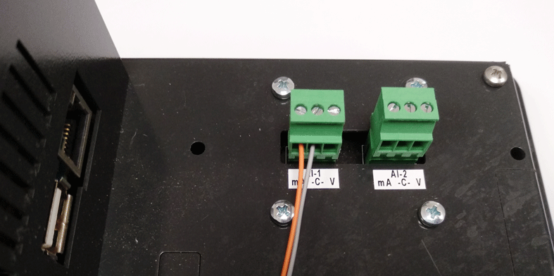
The Ltouch7 GS has 2 analog input channels, we can connect up to 2 PT100 sensors. In below example we connect 1.
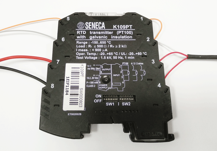
This is a close-up of our transmitter:
- PT100 connected with 3 wires, on terminals 2, 3, 4 as per Seneca datasheet. the sensor resistance is between terminal 2 and 3 (red and white wires)
- The converter needs a separate power supply and we connect the 24Vdc to terminals 7 and 8
- We connect the current signal coming out of the K109PT board to the analog input of our Ltouch7 GS. We must respect the polarity and so we connect the gray wire to the GND terminal of the Ltouch.
- The orange wire must be connected to the current mA terminal of the Ltouch
 Finally, the code for this setup is very simple. The following diagram measures the 0-20mA signals on channel 1, with a resolution of 17 bits, and maps the current over a temperature range. This mapping will depend on the transmitter, the example below maps from 0 mA to 0 degrees and from 20 mA to 100 degrees (constants defined by the dip switches).
You can use the library BMTouch to configure and read the values in to android studio.
View this for download library
View this for how to use BMtouch Library
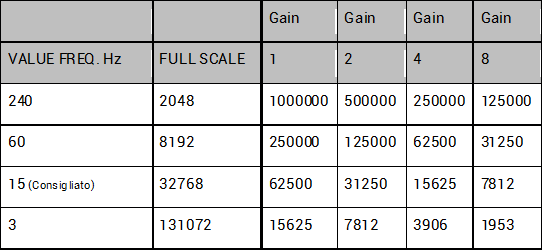
To configure the sampling frequency directly write the value of the frequency and scale through the library subito dopo protected void onCreate :
BMTouch.ADC_set_scale((byte) 0, (byte) 0, 1);

BMTouch.ADC_set_frequency((byte) 0, 15);
Now we can call the library function to read the analog value through a single call or by creating a TimerTask that executes this cyclically :
ch1_val = BMTouch.ADC_read_channel((byte) 0, (byte)0);
ch1_val returns the value read from 0 to 32768, it’s up to us to multiply it by 100 and divide by 32768 to find the temperature.
temp = (ch1_val*100)/32768;
that’s all, if you have any questions please contact us

